User Manual
MIRRA is a microclimate monitoring system that provides real-time access to microclimate data and consists of sensor nodes (which collect microclimate data from attached sensors) and gateway nodes (which receive microclimate data from sensor nodes and upload these on a web server). This manual explains the set-up of sensor nodes and gateway nodes for a MIRRA microclimate system. For showcases that demonstrates the potential of MIRRA, see these showcases: Canopy buffering, Formica experiment, Open Top Chamber experiment
Introduction and system components
MIRRA nodes consist of one main PCB that serves either as a sensor node on which different sensors can be connected, or as a gateway node that communicates between sensor nodes and the web server.
The current set-up of a sensor node consists of a soil temperature sensor connected directly to the MIRRA sensor node PCB and air temperature, relative air humidity and light availability sensors which are printed on two small, separate PCBs (i.e., the sensor hat). This sensor hat is then also connected to the main PCB of the MIRRA sensor as it is the main PCB that ensures the effective and regular sampling of the microclimate sensors, the saving of data and the sending of data to the MIRRA gateway node.
The MIRRA gateway node collects data from all MIRRA sensor nodes in the set-up through LoRa technology (LOng RAnge radio communication technique) and then sends the data further on to the MIRRA database via internet.
The figure below shows a MIRRA sensor node with the most important components indicated with labels.
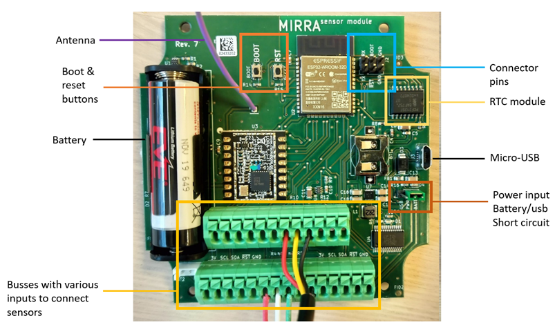
In this manual we walk you through the different steps to set-up a MIRRA system which include (to jump: use the sidebar):
• Programming PCBs as MIRRA sensor nodes or as a MIRRA gateway node
• Connecting gateway to cloud server
• Connecting MIRRA sensor nodes to the MIRRA gateway node
• Connecting microclimate sensors to the MIRRA sensor nodes and installation in the field
• Troubleshooting steps
Programming PCBs
The freshly bought and built PCBs must first be equipped with the correct MIRRA firmware. To do so, the firmware must first be built from the publicly available source code. This firmware blob can then be uploaded to the PCB’s processor. Through the UART command line interface, it is subsequently possible to ‘talk’ to the processor and change certain variables or execute specific functionalities. The following steps will guide you through each of these tasks in order to set up a full MIRRA installation.
Opening the MIRRA code in program Visual Studio Code (VSCode)
If using an external USB programmer (e.g. if your PCB version does not have a USB programmer on-board) and are operating on Windows, install this USB driver
Install Visual Studio code on your computer from here
Install the extension PlatformIO within VSCode from here
Either download the code from the MIRRA GitHub page (green button ‘<> Code’-> ‘download ZIP’) and save locally on your computer OR execute
git clone https://github.com/mirra-org/mirra(see here) if you have Git installed.Open Visual Studio Code
Open the code: ‘File’ button (top left) -> ‘Open folder’: select ‘MIRRA’ -> ‘code’ -> ‘MIRRA-main’ -> ‘firmware’
On the left side panel, you can now see the internal folder structure of ‘firmware’ and open different files by clicking on them.
Checking the pre-programmed settings for gateway and sensor nodes
Both gateway and sensor nodes have some predefined settings, such as sampling time interval, which are saved in the ‘config.h’ file. This enables the user to change these default values on the sensor and gateway nodes without further manual programming.
On the left side panel in VSCode, open the ‘config.h’ file within the gateway or sensor_node folder
Check out the settings, for example:
// s, time between sensor sampling for every node
constexpr uint32_t defaultSampleInterval = 20 * 60;
The sensor nodes will sample values from their microclimate sensors every 20 minutes.
// s, time between communication times for every nodes
constexpr uint32_t defaultCommInterval = 60 * 60;
The gateway will communicate with a node every 60 minutes.
Sampling interval and communication interval need to be attuned to each other. If the sampling interval is shortened, but communication remains at an interval of one hour, the sensor node would be sending much more data in one go. Therefore, if the sampling interval is shortened, also the communication interval should be shortened.
Setting up a sensor node
Connect the sensor node with your computer over USB. If using the external USB programmer, connect ground to ground and transmitter to receiver pins: GND-GND, TX-RX and RX-TX
Power the board using the USB supply by connecting the PWR pin to the USB pin
Plug button: choose the right port (e.g. COM4) and check this in Devices - Ports
Select the right environment: click button (bottom left) ‘Swith PlatformIO Project Environment’ and choose ‘env:sensor_node’ at the search bar on top of the screen.
Build all the code into binary format that can go on the sensor node. Click the button V (bottom left) ‘PlatformIO: Build’
Set upload settings. Click the cable button (bottom center) ‘Set upload/monitor/test port’ and choose ‘Auto’ at the search bar on top of the screen (or choose the port in which the node is shown in the device manager).
Put the sensor node in upload mode. Hold down the ‘BOOT’ button on the sensor node and push the ‘RESET’ button on the sensor node once.
Upload from VSCode. Click the arrow button (bottom left) ‘PlatformIO: Upload’ . This upload may take some time (1-2 minutes depending on firmware size), and may fail midway through because of communication issues. In that case, simply retrying will often fix the issue. If the upload does not start at all: verify that your port is selected correctly and that the PCB is powered correctly.
Go to the serial monitor. Click the cable button (bottom center) ‘Set upload/monitor/test port’ and choose ‘Serial monitor’ at the search bar on top of the screen.
Push ‘RESET’ button on the sensor node.
Power the board using the battery by connecting the PWR pin to the BATT pin.
Going in and out of command mode
Connect the node and select Serial monitor (cable button, see above).
Push the ‘BOOT’ button on the node.
You can now type commands, for example ‘printsample’ to make the sensor nodes sample their sensors and return the measured values. An exhaustive list is available here
After one minute of inactivity, the node will automatically quit command mode.
Setting up a gateway node
Set-up the gateway node and upload its firmware similar to the workflow described above for the sensor node, but replace the environment with ‘env:gateway’.
The gateway will most likely not have a correct internal time. To fix this, enter command mode on the gateway.
If the WiFi configuration that is specified in
config.his incorrect, execute thewificommand first: this will allow you to configure a new SSID and password.Execute the
rtccommand. The gateway will retrieve the current UTC time over WiFi via NTP.Change other parameters if needed (for example, check
intervals).
Connecting gateway to cloud server
After setting up the gateway, connect the gateway to the server. To do so, execute
serverin the command phase.You will be asked to enter the address of the server: mirra.ugent.be
You will be asked to enter the MQTT port
At the same time, navigate to your server’s Add Gateway page and enter its MAC address into the form. Once submitted, you will be given an access code which should be entered in the command mode interface. Afterwards, the gateway will attempt to connect to the server to test this newly configured connection. Note: this step may be executed even after nodes have been connected; collected data that has not been uploaded to the server will be transferred on the next connections.
Connecting sensor nodes to the gateway
Set up all sensor nodes as described above.
Set up the gateway similar to the workflow described above.
Go to the command mode of the gateway by pushing the ‘BOOT’ button on the node and execute the command ‘discovery’. The gateway will now constantly listen for incoming messages from nearby sensor nodes and add them to its schedule accordingly.
Push the ‘RESET’ button on the sensor nodes. On ‘RESET’, sensor nodes will automatically send out a message advertising its existence. Keep a close look on the gateway’s output, which will confirm if nodes have been successfully registered.
Once all nodes have been added, push the ‘BOOT’ button on the gateway to end its discovery mode.
If desired, view the gateway’s scheduling of all the sensor nodes using
printschedule.
Read out of a gateway
Connect through the micro-USB
Press BOOT (if no reaction: check RESET)
Command:
printdatato view sensor dataCommand:
printlogsto view logs
Connecting microclimate sensors to the MIRRA sensor nodes and installation in the field
Installing the sensor node in a watertight enclosure
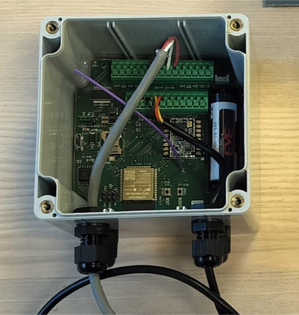
The MIRRA sensor node was developed to fit in a square watertight enclosure with a 105 mm side.
To allow sensor cables to enter the enclosure in a waterproof way, drill two holes of 12 mm diameter and install two cable glands. The glands should be installed on the upper half of the casing (not too far from the lid) and in the field, the glands are installed below the casing to limit risk of water.
After preparation of the cable glands, install the programmed MIRRA sensor node in the casing, with the 1w box on the other side of the glands, to allow additional spacing to guide the cables from the glands to the sensor node. The figure below shows a MIRRA sensor node installed in the waterproof enclosure with two cable glands (bottom) and the 1W1 box on the opposite side of the glands to allow cable installation.
Connecting the soil temperature sensor
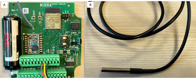
Connect the three wires from the soil temperature sensor to the 1W1 box of the PCB (red wire in 33V input, yellow wire in data input, black wire in ground input). The figure below shows A. the installation of the soil sensor on the 1W1 box with three coloured wires, B. Sensor end of the soil sensor cable that should be burried in the soil to measure soil temperature.
Connecting the sensor hat
The sensor hat consists of two small PCBs: an L sensor hat with a light sensor and the RHT sensor hat which contains an air temperature and relative humidity. To prevent water damage to these two small PCBs we protected the temperature and relative humidity sensors and the wire lines with silicone. To connect the sensor hat to the MIRRA sensor node:
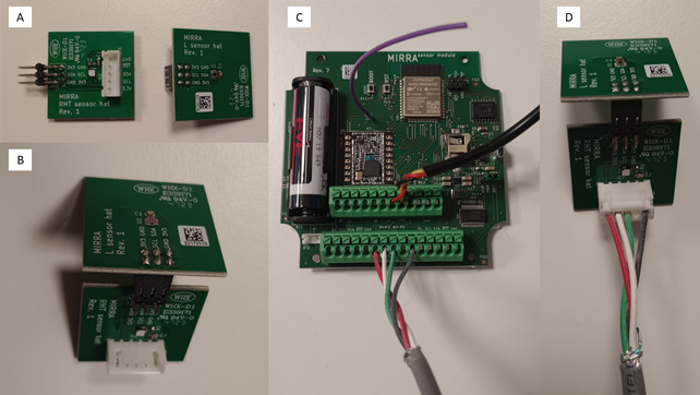
Connect the two small PCBs (L sensor hat withand RHT sensor hat) with microclimate sensors to each other, to form the sensor hat (Figure below a and b).
Connect a four-wire cable to the I2C box of the PCB (Figure below c) (black wire in ground input, RST input empty, green wire into SDA input, white wire into SCL input, red wire into 33V input).
Connect the cable to the sensor hat PCB with the temperature and relative humidity sensor (Figure below d)
The figure below shows (A) RHT sensor hat and L Sensor hat (B) are connected using the pins to form the sensor hat (C) Cable connection on the I²C box on the PCB (D) Cable connection on the sensor hat.
Preparation of a radiation shield
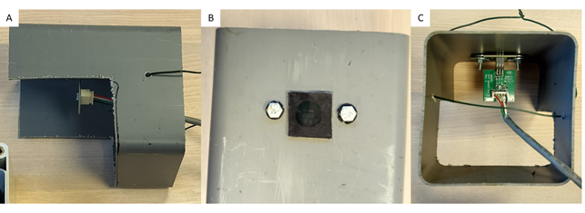
To avoid direct sunlight on the light sensor (risk of saturation) and on the temperature sensor (risk of sensor heating), it is important to install the sensor hat in a radiation shield. We prepared homemade radiation shields from a grey square pvc tube that was half cut to provide an open part that allows air ventilation. The design of the radiation shield can be tailored on the available material, but in our case (Figure below):
• We drilled a xx mm hole in the middle of the upper side to allow light to reach the light sensor.
• We pasted a photographic light filter (link) on top of the shield with glue to avoid saturation of the light filter and to prevent water entering the radiation shield.
• We drilled two small holes next to the light filter and installed a screw bolt with a rubber ring to be waterproof and then clamped the part of the sensor hat with the light sensor right below the opening with the light filter, by screwing a nut and an iron ring on the screw bolt.
• Finally we drilled two small holes on the rear side of the radiation shield to pass an iron wire to fix the radiation shield to a pole in the field.
The figure below shows a radiation shield with sensor hat: (A) side view, showing the general design and the holes for he iron wire to fix the shield in the field (B) top view, showing the light filter and the screw bolt with rubber ring (C) inside view, showing how the sensor hat is fixed on top of the radiation shield.
Installation of sensor node in the field
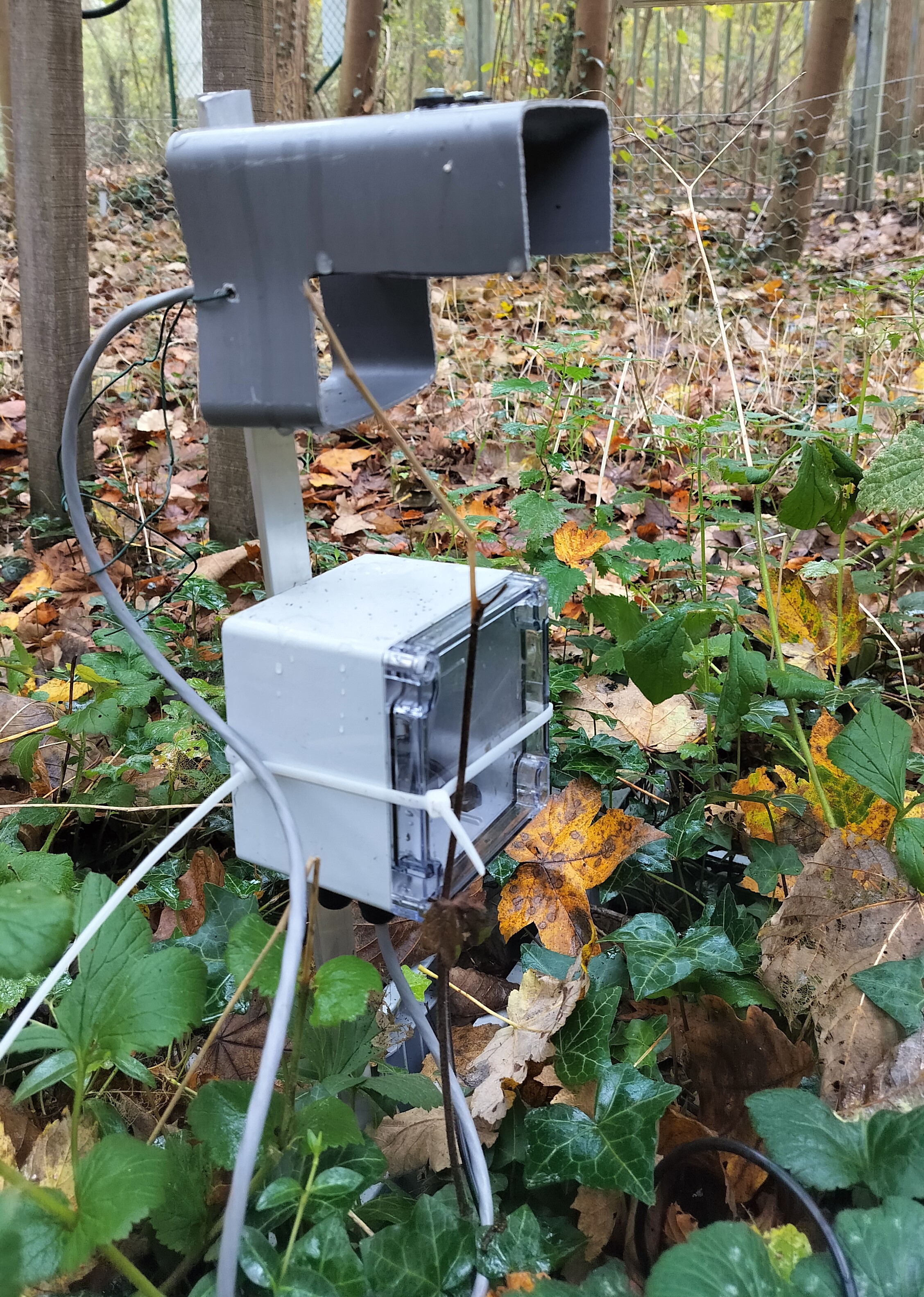
Installation of the MIRRA sensor node in the field can be tailored to the specific research questions, e.g., varying height of the sensors, or attaching to a study tree. As an example, we show how we installed the sensor nodes in the field (Figure below):
• We used an L-profile of stainless steel of 70 cm to install the sensor nodes in the forest.
• We drilled a screw through one side of the profile on top to support the radiation shield and a second screw 20 cm lower to support the casing of the sensor node.
• We put the L-profile 20 cm in the soil with a hammer. • We attached the radiation shield with an iron wire to the L-profile, making sure that the shield was resting on the top screw.
• We attached the waterproof casing with the sensor node with plastic straps, making sure that the casing was resting on top of the lower screw.
• We installed the soil sensor at 5 cm depth with help of a small concrete iron rod.
The figure below shows installation of the MIRRA sensor node in the field with radiation shield around sensor hat (top) and waterproof casing (middle) and the black cable with the soil sensor in the forest soil (bottom).
Troubleshooting
Gateway errors
- Connection to server not working
Ensure the WiFi network to which the gateway connects is working and stable. The gateway’s logs should tell whenever an attempted connection fails with “Could not connect to WiFi.”. Also ensure that the internet is actually accessible from this network. For example, if the rtc command seems to take forever or if the server command fails just after entering the access code, this may be a sign that there is no internet connection available on the network.
If the server has recently undergone major infrastructure changes (e.g. redeployment, reinstallation), then the PSK used by the gateway may no longer be accurate. Reconnect the gateway to the server by re-executing the server command and following the same steps as the initial setup.
The server will disallow connections if a significant time difference is detected between the server and the client (i.e. gateway). Recalibrate the gateway’s time using the rtc command as done in the initial setup. If this happens consistently, it might be because of a hardware issue in the gateway’s RTC module causing large time drifts.
- Communication with the nodes not working
Checking to see if the communication with nodes is successful can be done by checking the logs after a communication period. The gateway logs how many sensor data messages were received on a node-by-node basis, or if none were received at all.
If no data is received from any node, the culprit may be the gateway. Check the structural integrity of the gateway’s antenna, ensure the gateway is not located inside a Faraday cage or similar structure, …
In the event of a power cycle of the gateway, the RTC module may have reset, causing the time to be incorrect. This will always result in communication failures with the nodes. Recalibrate the gateway’s time using the rtc command.
If the gateway and/or nodes were moved after the initial “discovery” pairing, ensure that they have not been moved too far away.
In the event of sub-zero temperatures, communication will generally not work, as the radio module does not work under those circumstances. The module itself and its sensors should still function as normal, so this back-logged data should be sent when conditions are warmer again.
If only select nodes are exhibiting connection issues, then the issue(s) probably pertain to the nodes themselves.
Node errors
- I2C read error
When a node first wakes up from sleep, it first reads the current time from the node’s RTC module. This process occurs over I2C. On some nodes, this may intermittently cause an I2C read error, effectively locking the board in a fail state. The exact cause of this error is still unknown, though there are a few characteristics to watch out for:
Node variability: Some modules are more susceptible to this issue than others, which hints at it being a hardware-related issue.
Error early in the life cycle: Affected boards will have this error appear during either the programming phase, or the boot phase of the discovery pairing phase or the first few communication periods.
Persistent error: When encountering the I2C error and resetting the module (i.e. pressing RESET button), the error almost always repeats itself.
The most effective way to combat this error is to switch to a different module or attempt to reprogram the node. If the error occurs during the programming phase, rub the tips of your fingers on the pins of the RTC module that face the USB programmer while continually resetting the module. It seems that grounding some of the pins this way results in the RTC module properly resetting, allowing proper I2C communication to proceed. Even so, such fixes can be temporary, and the I2C error may reoccur on subsequent boots.
- Battery
The depletion of the battery is an inevitable mode of failure for the sensor nodes. Monitor the affected node and check if pressing the BOOT or RESET buttons trigger output on the terminal. It may be the case that the node seems “on” until it has to sample its sensors or send sensor data to the gateway, when it abruptly powers down. This is because the battery may provide enough voltage/power to start up the node, but reception/transmission is a far more power-hungry process which puts more strain on the battery, causing it to fail. If this is the case, or if there is no terminal output at all, remove the battery.
Check the removed battery’s voltage level with a voltmeter/multimeter: below ~3.1V, it should not be able to operate the sensor node.
Replace the battery as necessary.
Other hardware issues
If communication is successful, but there are missing, nonsensical or NaN sensor data values, then there might be a hardware issue with the individual sensors.
Verify that the connections from the sensor board to the sensors are still properly intact.
Check for damage on the light/air temperature sensor, especially water damage. Ensure that none of the pins touch each other.
Viewing logs
Logs can be displayed on both gateways and sensor nodes using the printlogs command, which dumps the entire content of the available logging data to the serial outpu, which can take some time. This will generally be too much data for the PlatformIO terminal to display at once, but logs (and the entire monitoring session) are also automatically kept as a file in the logs folder under the name device-monitor-XXXXXX-xxxxxx.log, specifying the date and time of the monitoring session.